Aenean ornare velit lacus, ac varius enim lorem ullamcorper dolore aliquam.
The advantage of using thin film sensors over conventional foil gauges is that these can be directly deposited on the substrate without requiring an external adhesive between the substrate and the sensors. We can eliminate creep and hysteresis errors that occur with time by eliminating these adhesive bonding agents. This project was a part of the Ministry of Mines (the Government of India) initiative to replace traditional foil-based strain gauges with thin-film strain gauges for gas turbine blades. In addition to a thin film strain gauge, a thin film thermocouple was also pursued.
An insulation layer becomes necessary to achieve the direct deposition of a strain gauge onto the turbine blades as both the strain gauge and the turbine blade materials are metallic which would create a problem in measuring the change in resistance of the strain gauge. Also, to prevent delamination of the layers at higher temperatures a second layer of coating called the bond coat is required which balances the coefficients of thermal expansion of the substrate and the insulation coating.
In this project, I started by choosing the materials for the thermocouple, strain gauge, bonding coat, and insulation coat and finalized the architecture for the thermocouple and strain gauge. Further, with the use of Direct Current/Radio Frequency magnetron sputtering and a solution precursor plasma system with a single arm ABB robot using ROS, I optimized the deposition parameters for the above gauges and coatings. Further, various technologies for extracting lead wires from the sensors were explored. Finally, I designed a test setup for calibrating the new sensors using LabVIEW.
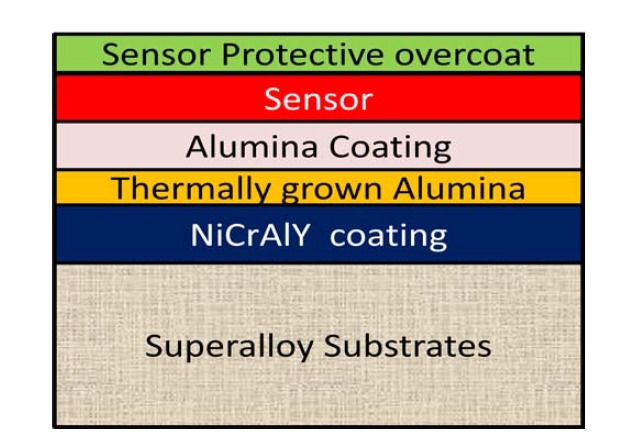
In this project we aim to deposit thermocouples and strain gauges on IN718 turbine blades, the challenge being the conductive nature of IN718, making it indistinguishable from gauge-induced changes. To overcome this, Alumina (Al2O3) is chosen as an insulation layer due to its high-temperature tolerance and electrical insulation properties. However, the mismatch in thermal expansion coefficients between Alumina and IN718 could lead to delamination. To address this, a Nickel Chromium Aluminium Yttrium (NiCrAlY) alloy layer is introduced, acting as a bond coat to prevent delamination at high temperatures. The final protective layer for the sensors also consists of Alumina. This multi-layered approach ensures accurate sensor readings and protection.
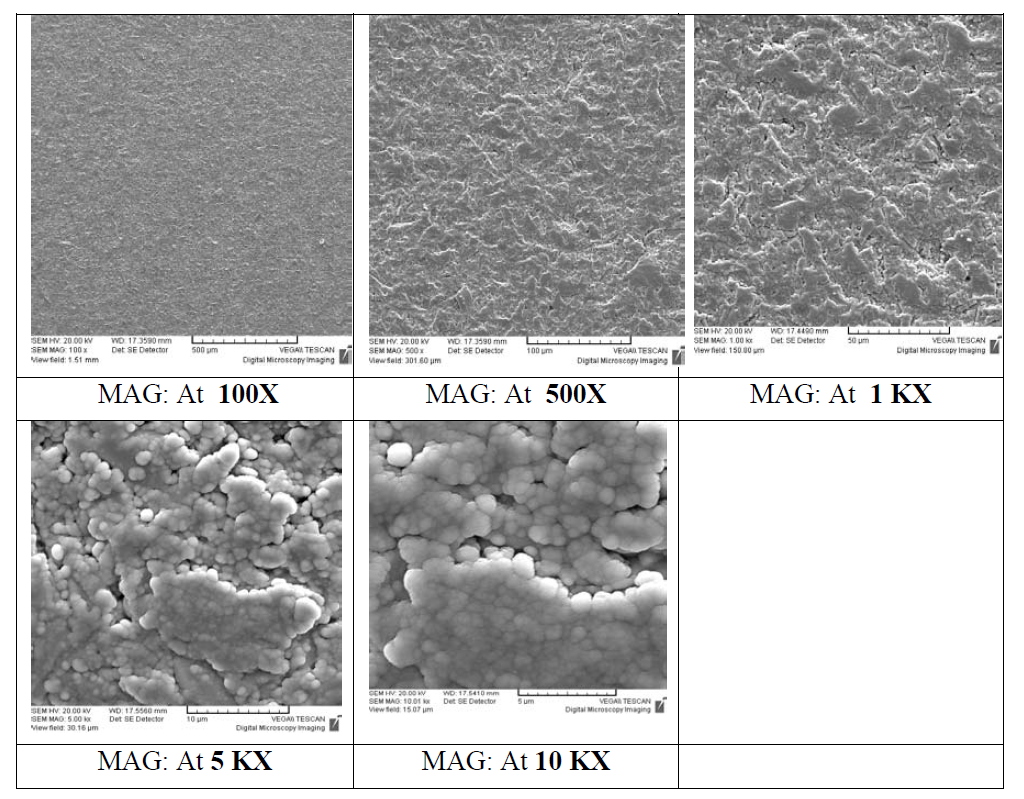
The bond coat was deposited through DC Magnetron sputtering, and the parameters were optimized. The resultant microstructure from SEM is as shown in the figure. Similar characterizations were also done for other coatings throughout the project.
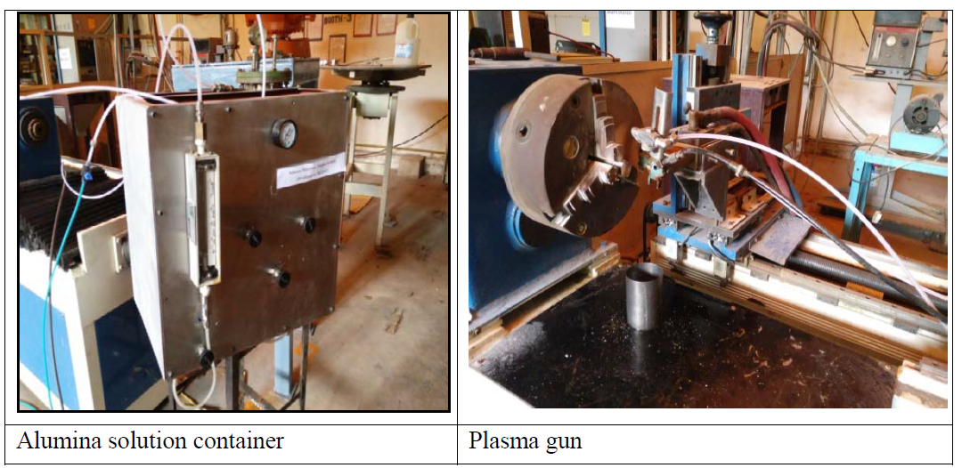
The insulation coat was chosen to be Alumina and this was deposited by using plasma spray method using ABB robot which was developed inhouse at NFTDC. There are two main parts, the first one being the plasma gun and the second one is the solution container. The solution container is where we pour our precursor of Alumina into. Once the solution container is filled completely we need to check the pipe connections towards the plasma gun where the spray is needed. When the plasma is turned on we need to be able to spray it so that it vaporizes the Alumina and forces it on to the substrate. The plasma must not be on for more than 45 seconds as it would erode the material around it. The plasma gun was mounted over the ABB robot and the deposition was carried out by using ROS.
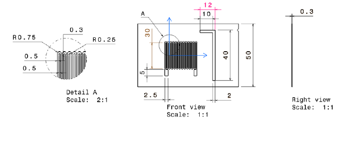
It was chosen to manufacture a gauge of 350 Ω resistance and to obtain this, a necessary mask must be developed so that a gauge can be deposited perfectly. The number of legs and the thickness were calculated to obtain the value of 350 ohms. Laser cutting was used to manufacture these shadow masks.
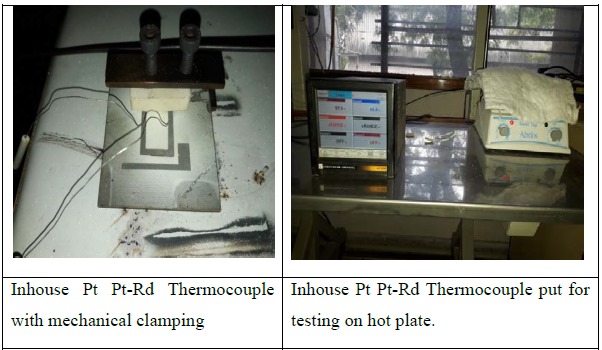
The Thermocouple was made by using Pt Pt-Rd Materials and was sputtered on a substrate which was plasma coated with Alumina and Sputtered with NiCrAlY alloy. The base substrate used was SS316. It was then clamped using a lead wires mechanically. The testing of this thermocouple was done using a EurothermChesselle DAQ channel and compared with a commercial K-Type Thermocouple. The test was conducted on a ABDOS hot Plate and covered using Glass wool to prevent any heat loss occurring to the surroundings. The thermocouple responded very well with an error of plus or minus 5degrees. But compared to the K-type thermocouple it needed a little more time to reach the temperature indicating that the response time was still more than K-Type thermocouple. Also as mechanical clamping was done there could be additional heat losses to the C clamp.
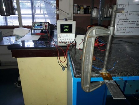
Initial tests were performed for the deposited strain gauge on a Kaptan tape by using a Keithley ohmmeter. Compared to the theoretical calculations, an error of about 6% was noticed which could have been due to the experimental inaccuracies. A hysteresis was observed while loading and unloading and also creep was observed as the loading cycles increased. This was due to the inflexibility of the Kaptan tape.
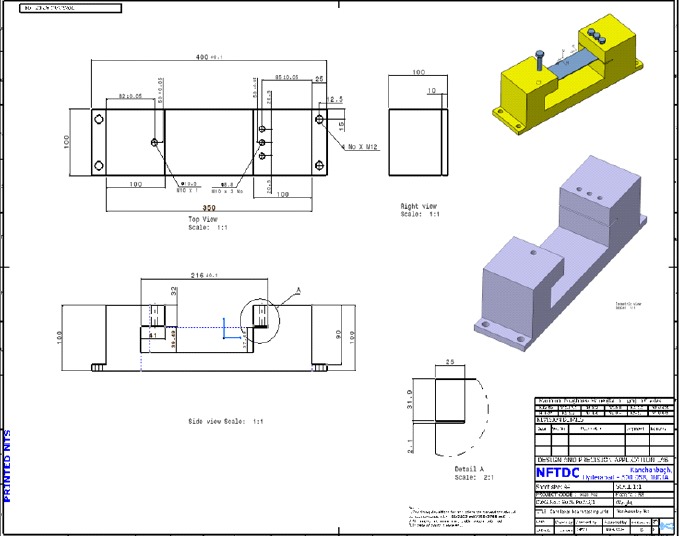
As mentioned, the earlier setup that was used is not a very accurate method as the position of application of load keeps changing when we try to change the weights. This brings in a lot of errors into our testing. For this reason, a testing system for cantilever samples was developed. The design can hold the cantilever sample in the slot provided in it and can deform it by a specified amount of deflection. The design uses a micrometer to move the free end of the cantilever by 1mm every time.
