Aenean ornare velit lacus, ac varius enim lorem ullamcorper dolore aliquam.
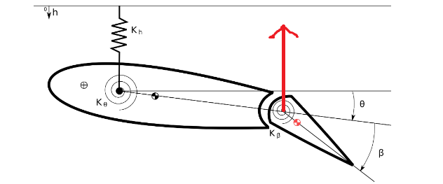
For changing the direction of an aircraft, pilots usually use the additional lift generated by changing the configuration of the control surfaces to get a moment which would then help in turning the aircraft. This, however, presents another problem which might decrease the total lift generated by the wing. To understand this, let us have a look at Figure 1 which shows a typical section with a flap.

As you can see, the lift which is generated by adjusting the control surface is not at the elastic axis, but instead at the hinge point. This gives a moment that tries to bring down the nose of the typical section thereby decreasing the flexible angle of attack. The additional lift that the pilot tries to generate by adjusting the control surface is now compromised to an extent because of the decrease in the flexible angle of attack.
Depending on the ratio of these changes, there could be a point when adjusting the control surfaces will no longer generate any additional lift as the loss in flexible angle of attack has negated that. This is the point of control reversal and beyond this point, any increase in beta will give the opposite effect compared to the intended one. For example, trying to take a left turn might turn the aircraft towards the right.
Compared to other aeroelastic phenomena like flutter or divergence, control reversal is not catastrophic but studying it would give an understanding at what point would the plane behave erratically. Once the point of control reversal is known, then the pilot should steer the plane in the opposite direction to achieve the desired result. Also, the understanding of this point is important as around the point of control reversal, the effectiveness of the wing is very low. In fact, the effectiveness of the wing improves after crossing the control reversal point and this could be highly desirable in cases like fighter planes where maneuverability is critical but for commercial planes, they are always designed below the control reversal point.
To find the point of control reversal, we start by comparing the ratio of the lift generated by a flexible wing to the lift generated by a rigid wing, and then equating it to zero as that is the condition of control reversal.
The above equation gives the effectiveness of a control surface. This is the equation that we will be using to plot the effectiveness against the dynamic pressure. Next, to find the ratio of \( \frac{\theta}{\beta} \), let us write the moment equilibrium about the elastic axis.
where,
Substituting \( M_{AC} \) and \( \text{Lift} \) into the moment equilibrium equation will enable us to find the ratio of \( \frac{\theta}{\beta} \). Substituting this into the equation of effectiveness will give:
As you can observe from the above equation, if the denominator becomes zero, then \( \theta \) becomes infinity. This is the condition for divergence. However, if the numerator becomes zero, then the total lift generated by the control surface and the wing due to its deformation becomes zero, making the effectiveness zero or signifying the beginning of control reversal.
Substituting and equating the numerator to zero for finding \( q \) that corresponds to \( q_{\text{reversal}} \), we get:
The reversal dynamic pressure in the equation is negative because \( C_{M_{AC_\beta}} \) is negative.
In the graph below, you can adjust the values of the typical section parameters and the torsional stiffness to get the effectiveness curve up to 1.5 times the reversal pressure. Sometimes, you can observe anomalies in the behavior of the graph when modifying different parameters. Remember that this is not the only problem pertaining to a typical section. Divergence might occur before control reversal may occur, and this would lead to these anomalies in the graph below. Adjusting the other parameters should resolve it, provided there is a sufficient range available for the other parameters.
Normally, to achieve a desired lift, one or a few of the several control surfaces are adjusted. As seen earlier, each of these is limited by the dynamic pressure and the typical section parameters. Designing each of these control surfaces differently would then give us a better operating window over a range of velocities or dynamic pressures, reducing the problem of control reversal.
Another solution that is not usually employed is the use of forward-swept wings. This is primarily due to the reason that they are much worse for divergence compared to backward-swept wings and with control reversal not being catastrophic, risking the chance of a catastrophic failure with divergence through the use of forward-swept wings is not logical.